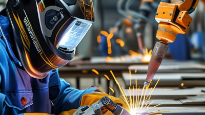
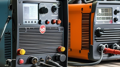
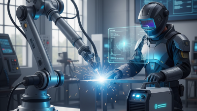
A Mig Welding Machine, commonly called a MIG welder, joins metal through a continuously fed wire electrode. An electric arc melts the wire and the base metal. Shielding gas protects the molten pool from oxygen and nitrogen. The result can look like a narrow, bright bead moving across steel.
Welding engineer John C. Villafuerte explains, “Gas metal arc welding uses a continuously fed wire electrode and an externally supplied shielding gas.” This simple description reveals the machine’s central design. The wire feeds through the gun. The trigger starts electrical current, gas flow, and wire movement. Operators adjust voltage, wire speed, gas flow, and travel speed. Small changes matter. A slow hand can produce excessive heat. A fast hand may leave an incomplete joint.
The process is popular in automotive repair, fabrication shops, construction, and home workshops. It works efficiently on mild steel, stainless steel, and aluminum, when the correct wire and gas are selected. Yet MIG welding is not automatically easy. Clean surfaces, proper grounding, and suitable settings still determine weld quality. That point deserves attention. Many beginners trust the machine too much and inspect the bead too little.
This guide explains what a Mig Welding Machine is, how its components work, and why technique affects safety and strength. It also considers common mistakes, practical adjustments, and the limits of this versatile welding process. A clean bead helps. A tested joint matters more.
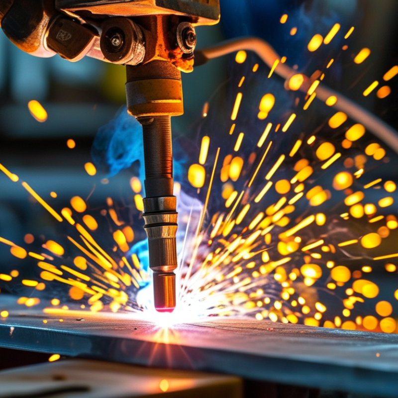
A MIG welding machine uses Gas Metal Arc Welding, or GMAW, to join metal with heat from an electric arc. The arc forms between the workpiece and a continuously fed wire electrode. This wire melts and becomes part of the weld joint. Unlike a separate welding rod, it does not need frequent replacement. That makes the process practical for long seams and repeated fabrication work.
The machine feeds the wire through a gun at a controlled speed. At the same time, shielding gas flows around the arc and molten weld pool. This gas limits contact with oxygen and nitrogen, which can cause porosity, oxidation, or a weak bead. Common gas choices include carbon dioxide, argon, or a mixture of both. The correct selection depends on the metal, wire type, and required weld appearance.
In the workshop, clean surfaces matter more than many beginners expect. Paint, oil, and rust can disturb the arc and trap defects inside the joint. Voltage, wire speed, travel angle, and gas flow must work together. Too much wire speed can create a harsh, uneven arc. Too little gas may leave tiny holes in the bead. A steady hand helps, but technique alone cannot fix incorrect settings. It is easy to blame the machine first. Careful inspection often reveals poor preparation instead. Welders should also check the manual, use suitable protective equipment, and test settings on scrap metal before touching the final workpiece.

A MIG welding machine joins metal by feeding a continuous wire through a torch while an electric arc melts the wire and workpiece. The power source converts input electricity into controlled welding current. Modern reports from Grand View Research estimate the global welding equipment market will continue expanding through 2030, driven partly by automated and semi-automated processes. That growth reflects a practical advantage: MIG welding reduces frequent electrode changes and supports steady production.
Wire diameter affects heat, penetration, and control. Common sizes range from 0.6 to 1.6 mm. Thin 0.6–0.8 mm wire suits light sheet metal, while 1.0–1.2 mm wire handles general fabrication. Larger 1.6 mm wire needs higher current and stronger machines. The feeder must push the wire smoothly, without crushing it. Roll pressure matters. Too much pressure deforms the wire; too little causes slipping. The torch carries the wire, current, shielding gas, and trigger signal. A short, clean contact tip improves arc stability, although beginners often blame the power source too quickly.
Tips: Check liner cleanliness before increasing voltage. Set wire speed and voltage together. Watch the sound; a steady frying noise usually indicates a balanced arc. In workshop testing, small gas leaks can ruin an otherwise correct setup. Keep the torch angle near 10–15 degrees for many fillet welds. This is not universal. Joint shape, position, and material still demand judgment. Data from the American Welding Society also emphasizes procedure control and operator skill, reminding us that equipment specifications cannot replace practical inspection.
| Core Component | Primary Function | Typical Data or Range | How It Works in the MIG Process | Key Selection Considerations |
|---|---|---|---|---|
| Power Source | Converts input electricity into controlled welding current and voltage. | Input: single-phase or three-phase AC Output: commonly 30–400 A Polarity: usually DC electrode positive |
Maintains a relatively constant arc voltage while supplying current to melt the continuously fed electrode wire. | Match the output range, duty cycle, input supply, and control functions to the material thickness and expected workload. |
| Welding Wire Electrode | Acts as both the consumable electrode and, in most applications, the filler metal. | Common diameters: 0.6, 0.8, 0.9, 1.0, 1.2, 1.6 mm Typical materials: mild steel, stainless steel, aluminum |
The wire is energized as it enters the arc. Heat melts the wire and base metal, forming a weld pool that solidifies into the joint. | Smaller wire is suited to thinner sheet and lower current; larger wire generally supports higher deposition rates and thicker materials. |
| Wire Feed Unit | Pushes the electrode wire from the spool to the welding torch at a controlled speed. | Drive arrangement: commonly two-roll or four-roll Control: wire feed speed in m/min or in/min |
The motor-driven rolls grip the wire and regulate its delivery. Wire feed speed strongly influences welding current and deposition rate. | Use the correct drive rolls, liner, and tension for the wire diameter and material. Excessive tension can deform soft wire. |
| Welding Torch / Gun | Guides the wire, transfers welding current, and directs shielding gas toward the arc. | Typical duty: air-cooled or liquid-cooled Common consumables: contact tip, nozzle, diffuser, liner |
When the trigger is pressed, the torch can initiate wire feeding, energize the circuit, and open the shielding-gas valve. | Select torch capacity according to welding current and duty cycle. Keep the contact tip, nozzle, and liner clean to maintain stable wire delivery. |
| Contact Tip | Transfers electrical current from the torch to the moving electrode wire. | Sizing: matched to the wire diameter Material: commonly copper-based alloy |
The wire slides through the electrically conductive tip before entering the arc. The tip must provide consistent electrical contact without restricting wire movement. | A worn, blocked, or incorrectly sized tip may cause burnback, erratic arc behavior, and poor wire feeding. |
| Shielding Gas System | Protects the molten weld pool from atmospheric oxygen, nitrogen, and moisture. | Common gases: carbon dioxide, argon-rich mixtures, argon Typical flow: approximately 10–25 L/min |
Gas flows through the torch nozzle and forms a protective envelope around the arc and weld pool. | Gas choice affects penetration, spatter, arc stability, and bead appearance. Excessive flow can create turbulence and draw in air. |
| Gas Regulator and Flowmeter | Reduces cylinder pressure and controls the shielding-gas flow delivered to the torch. | Measurement: L/min or cubic feet per hour Typical working pressure: set according to the gas system and equipment instructions |
The regulator lowers high cylinder pressure to a usable level, while the flowmeter indicates or adjusts the gas volume reaching the torch. | Check connections for leaks and set flow while the gas is actually flowing through the torch. |
| Control Panel | Allows the operator to set and adjust welding parameters. | Common settings: voltage, wire feed speed, inductance, gas pre-flow, post-flow, burnback | The control system coordinates the power source, wire feeder, and gas valve to produce a repeatable arc and controlled weld start and stop. | Synergic programs can link voltage and wire feed speed, while manual controls provide more direct parameter adjustment. |
| Ground Cable and Work Clamp | Completes the electrical welding circuit between the workpiece and the power source. | Connection: workpiece to negative terminal in common solid-wire MIG setups Requirement: clean, secure metal contact |
Current travels from the power source through the wire and arc into the workpiece, then returns through the clamp and ground cable. | Remove paint, rust, oil, and scale from the clamp area. A poor connection can cause arc instability and excess heating. |
| Duty Cycle | Indicates how long a machine can weld within a specified time period before thermal protection may activate. | Common reference: 10-minute test period Example: 60% duty cycle permits approximately 6 minutes of welding followed by 4 minutes of cooling at the rated output |
Thermal sensors monitor internal temperature and may reduce or stop output if the machine exceeds its rated operating limits. | Compare duty-cycle ratings at the actual current required, not only at the machine’s maximum output. |
| Arc Parameters | Control heat input, penetration, bead shape, and deposition behavior. | Voltage: commonly about 15–32 V for many short-arc applications Wire feed speed: varies with wire diameter and current requirement |
Voltage primarily influences arc length and bead profile, while wire feed speed largely controls welding current and metal deposition. | Use manufacturer-approved parameter ranges, then fine-tune for joint position, material thickness, wire type, and transfer mode. |
| Transfer Mode | Describes how molten wire metal moves across the arc into the weld pool. | Modes: short-circuit, globular, spray, and pulsed spray Application: depends on wire, gas, current, and material |
Short-circuit transfer uses repeated wire-to-pool contact, while spray and pulsed transfer move smaller droplets across a more continuously maintained arc. | Short-circuit transfer is widely used for thin material and out-of-position work; spray-based modes generally require higher settings and suitable shielding gas. |
| Cooling and Thermal Protection | Removes heat from internal components and protects the machine or torch from overheating. | Torch cooling: air-cooled for lower-to-moderate loads; liquid-cooled for higher sustained loads Protection: thermal shutdown or output reduction |
Fans, heat sinks, or coolant circulation carry heat away from the power electronics and torch assembly. | Keep ventilation openings clear and use a torch with sufficient current capacity for the planned welding cycle. |
AMIG welding machine joins metal by feeding a continuous wire electrode through a gun. The power source provides direct current, while shielding gas protects the arc from oxygen and nitrogen. When the trigger is pressed, the wire advances toward the workpiece. A tiny gap remains. As the wire touches the metal, current creates a brief short circuit. The wire retracts, and an arc forms across the gap. Its heat can exceed 5,000°C near the arc core. The wire tip melts, while the base metal begins to liquefy. The result is a bright, moving molten pool. It is not a silent process. The arc crackles, and small sparks may scatter nearby.
As the gun moves, droplets transfer from the wire into the pool. Travel speed, voltage, wire feed speed, and gun angle shape penetration and bead width. A steady hand matters. Too fast can leave a narrow, poorly fused bead. Too slow may cause burn-through on thin sheet. Shielding gas must flow evenly, but drafts can disturb it. Clean metal reduces porosity, although real workshops are rarely perfect. A harsh, uneven hiss often signals unstable settings or poor gas coverage. Even experienced operators inspect fusion, bead shape, and spatter while adjusting their technique. No setting works perfectly every time. Thin steel still exposes small mistakes.
A MIG welding machine feeds a continuous wire electrode through a gun. An electric arc melts the wire and the workpiece, forming a joint as the metal cools. The shielding gas flows around the arc and keeps oxygen and nitrogen away from the molten pool. Without that protection, welds can become porous, brittle, or visibly rough.
A mixture of 75% argon and 25% carbon dioxide offers a practical balance for mild steel. Argon helps produce a stable arc and smoother bead appearance. Carbon dioxide adds penetration and supports stronger arc action. In a workshop, this blend often creates a controlled spray or short-circuiting arc, depending on voltage, wire size, and transfer settings. The bead may look flat and clean when the gun angle stays consistent.
Small adjustments matter. Excessive gas flow can create turbulence and pull air into the weld. Too little flow may leave pinholes along the bead. Drafts near an open door can cause similar problems. I have found that clean steel and a steady travel speed sometimes improve quality more than increasing gas flow. Yet this mixture is not perfect for every thickness or position. It can produce more spatter than an argon-rich blend, especially when voltage and wire speed are poorly matched. That roughness is easy to blame on the gas, but the settings may be the real cause. A dull, irregular bead deserves inspection before changing the cylinder.
A 75% argon / 25% carbon dioxide blend generally provides a smoother, more stable arc and lower spatter than pure CO₂, while pure CO₂ can produce deeper penetration with a harsher arc and more spatter.
Comparative rating: 1 = lower performance, 5 = higher performance. Ratings represent typical GMAW behavior and can vary with welding current, wire diameter, material thickness, travel speed, and machine settings.
A MIG welding machine feeds a continuous wire through a torch while shielding gas protects the molten pool. Its operating variables decide whether the bead looks smooth or uneven.
Current mainly follows wire feed speed. More feed usually creates more amperage and deeper penetration. Voltage controls arc length and bead width. Too much voltage can produce a flat, spattered bead. Too little voltage may cause stubbing and an unstable arc.
The AWS Welding Handbook identifies these variables as closely connected, not independent settings.
Travel speed changes heat input. A slow hand can create excessive penetration, undercut, or a wide bead. Moving too quickly may leave poor fusion.
A practical heat-input relationship is Q = ηVI divided by travel speed, where η represents arc efficiency.
The International Electrotechnical Commission standard IEC 60974-1:2017 rates duty cycle over a 10-minute period. A 60% duty cycle allows six minutes of welding, followed by four minutes of cooling at the rated output.
Real workshops are less tidy. Stops, starts, and joint preparation also affect machine temperature.
Tips: Begin near the procedure sheet’s recommended current and voltage range. Watch the puddle, not only the digital display.
Keep a consistent torch angle and travel distance. If the bead looks acceptable, still inspect the root and sidewalls.
A short test weld on matching material can expose poor settings before production begins.
Duty cycle ratings also depend on ambient temperature, so a hot workspace may reduce practical runtime.